Editing tri-meshes
Tri-meshes are surface representations in your fault and structural models. Even if your surface input data is in some other format, such a polyline sets, the required tri-meshes will automatically be generated from these, and in most cases ensure that the resulting models are accurate and consistent, and that the intersections between faults and horizons are clean and consistent. There may be cases, however, when you want to clean up intersections or make other tweaks to your tri-meshes. The floating palette (Tools > Editing Tools at the right of the Strip) contains a broad set of tools for accomplishing this graphically in your 3D View.
 Add Triangle (Shortcut key: A) Add a new triangle to a tri-mesh, to fill a hole or create a cleaner edge for example. The sides of the new triangle are formed between the locations (three) where you click. If you select the option 'Snap to node' you are ensured that the new triangle will be formed between existing nodes (your new triangle will be snapped to the existing nodes). However, if you do not select the option 'Snap to node' and you click further away of an existing node, a new node is created (not recommended).
Adding triangles; before and after click to enlarge
 Remove Triangle (Shortcut key: Ctrl+A) Remove a triangle from a tri-mesh. Select the tri-mesh and then select the tool. In your 3D View, click on the triangle you want to remove.
Removing triangles; before and after click to enlarge
 Remove Triangle Patch (Shortcut key: P) Remove a tri-mesh patch, or a complete tri-mesh. Select the tri-mesh and then select the tool. In your 3D View, click on the triangle patch you wish to remove.
Removing a triangle patch; before and after click to enlarge
 Flip Triangle Edge (Shortcut key: F) Flip (rearrange) the edge between two adjacent triangles. Select the tri-mesh and then select the tool. Click in your 3D View on the triangle edge you want to flip.
Before and after flipping edges click to enlarge
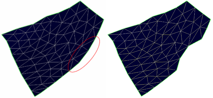
 Remove Edge (Shortcut key: Ctrl+K) Remove a triangle edge and its two connected nodes from the tri-mesh. The triangles around it are automatically rearranged. Select the tri-mesh and then select the tool. Review the additional settings, then click on a triangle edge to collapse that edge.
Lock node connections Ensure that the intersection remains watertight after editing the tri-mesh. To use this, you must already have a watertight intersection (fault to fault or horizon to fault).
 Split Triangle Edge (Shortcut key: Ctrl+F) Add a node to a selected triangle edge, splitting it in two. Select the tri-mesh and then select the tool. Review the additional settings, then click on the triangle edge you want to split.
Lock node connections Ensure that the intersection remains watertight after editing the tri-mesh. To use this, you must already have a watertight intersection (fault to fault or horizon to fault).
Splitting triangle edges; before and after splitting three edges click to enlarge
 Remove Triangles Under Line (Shortcut key: L) Draw a line on the tri-mesh and remove all the triangles under this line. Select the tri-mesh and then select the tool. In your 3D View, click to mark the beginning of the line and click a second time to end the line. All the triangles under the line will be removed.
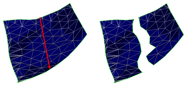
Removing triangles along a line: Before and after click to enlarge
 Cut Triangles Under Line (Shortcut key: Ctrl+L) Draw a line on the tri-mesh and remove the underlying tri-mesh area up to a specified distance from the line. The triangles surrounding the newly formed empty channel will automatically be rearranged. Select the tri-mesh and then select the tool. Now set the distance over which you want to cut the underlying tri-mesh in the 'Settings' section of the floating palette. In your 3D View, click to mark the beginning of the line and click a second time to end the line. All the triangles up to the specified distance from the line will be removed.
 Move Triangles (Shortcut key: T) Move one or more selected triangles freely around, along an axis or along the normal of the surface. Select the tri-mesh and then select the tool. In your 3D View, click on the triangles you want to move. Hold down the combination of ED, ND or NE keys and drag to move the triangle along the respective planes. For example, holding NE keys and dragging the triangle will restrict the movement in Northing - Easting plane while not allowing change in the depth. You can also use Shift key and drag the triangles to move them along the normal of the selected triangle.
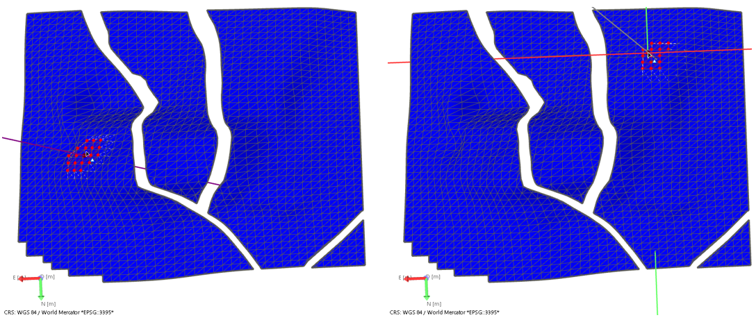
Examples of moving triangles: (Left) Moving the selected triangles along the normal. (Right) Moving the selected triangles in the Northing-Easting (NE) plane. click to enlarge
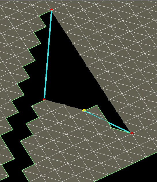
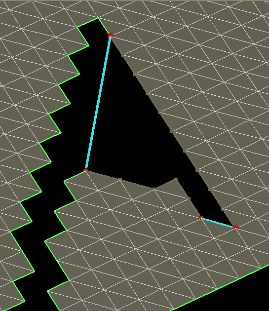
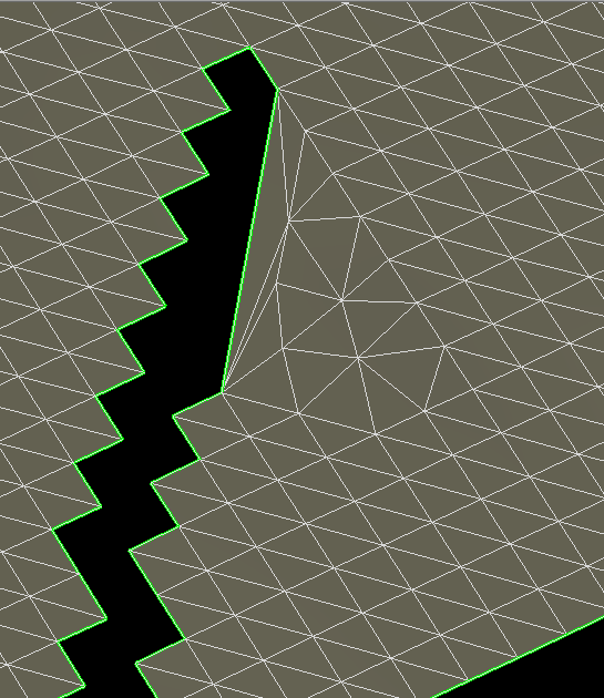
 Extend Boundary (Shortcut key: B) Extend the boundary of a tri-mesh by generating new triangles, either along the same dip (using the Ctrl key) or with a different dip (using the Shift key). To use the tool:
- Select the tri-mesh and then the Extend Boundary tool.
- In your 3D View, click on the boundary of a tri-mesh.
- Optionally click on the red dot at one end of the boundary to adjust (shorten or extend) the part of the boundary that will be modified. The red dot turns yellow to indicate it is selected. Click a second time on a different node along the boundary to apply this adjustment.
- You can now adjust the distance over which the boundary will be extended by holding down the Ctrl key and dragging the boundary. The boundary will extend in the direction of the tri-mesh plane.
- Alternatively, you can hold down the Shift key and drag the boundary. The boundary now moves along the normal of the tri-mesh, allowing you to change the curvature of the tri-mesh extension.
- To complete the extension, double click on the boundary segment.
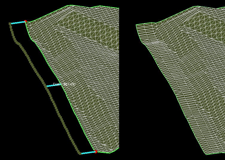

Extending the boundary of a tri-mesh click to enlarge
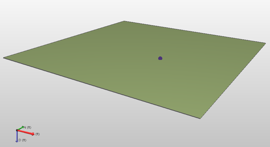
 Move Boundary (Shortcut key: Ctrl+B) Move the boundary of a tri-mesh by rearranging existing triangles. To use this tool:
- Select the tri-mesh and then the Move Boundary tool.
- Click on the tri-mesh to create a 'hinge point'. The tri-mesh will be curved from this hinge point towards the boundary that you are going to move.
- Click on the boundary to be moved.
- Hold down the Shift key and drag the highlighted boundary segment to move it along the normal of the tri-mesh. Release the mouse and Shift key when you are happy with the new boundary location.
-
To finalize the new boundary, double click the boundary segment.
Optionally click on the red dot at either end of the selected boundary to adjust (shorten or extend) the part of the boundary to be modified. The red dot turns yellow to indicate it is selected. Click on the new end node (somewhere along the boundary) to apply the shortening or extension of the boundary.
The hinge point is visible click to enlarge
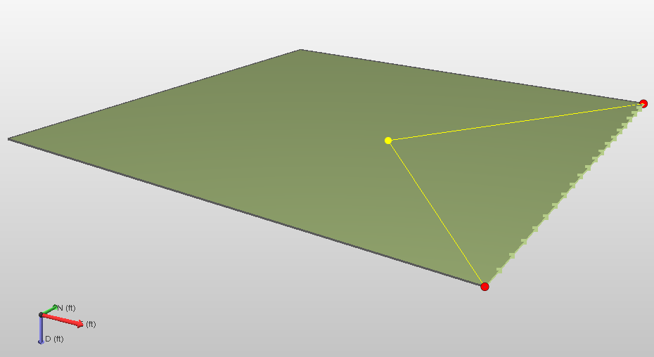
The boundary to move is selected click to enlarge

Moving the boundary along the normal of the tri-mesh click to enlarge
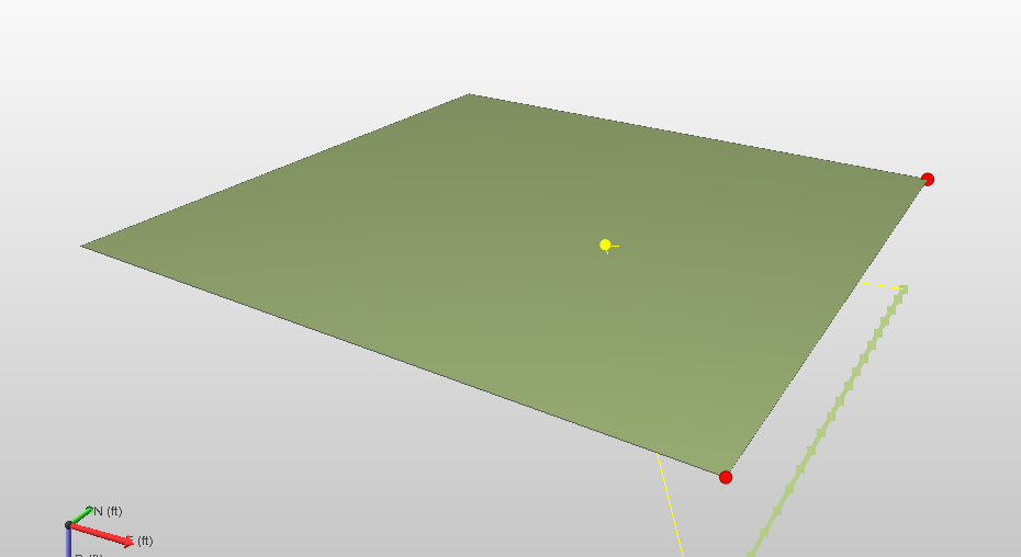
A preview of the new boundary location click to enlarge
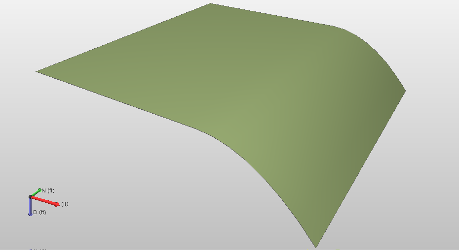
Result click to enlarge
 Connect Boundaries (Shortcut key: Shift+H) Fill (parts of) empty spaces in a tri-mesh. To use the tool:
- Select the tri-mesh and then the Connect Boundaries tool.
- Click on one of the boundaries. The ends of the segment that will be connected are shown by two red nodes.
- Click on the second you want to connect the first boundary to. The ends of this segment are shown by two red nodes, and blue lines indicate the extent of the connection of the boundaries.
- Optionally left click on a red dot at the end of the selected boundary to adjust (shorten or extend) the part of the boundary that will be modified. The red dot turns yellow. Left click a second time on a move the end node.
-
To complete the connection, double click on the tri-mesh.

Original situation click to enlarge

Node selected for moving click to enlarge

Both segments changed click to enlarge

Result click to enlarge
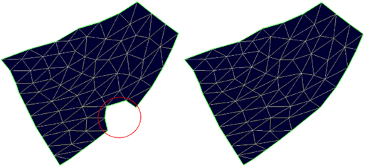
 Fill Hole (Shortcut key: H) Close a hole. The hole is closed with new triangles connecting existing nodes (no new nodes are created). Select the tri-mesh and then select the tool. Click on the edge of the hole and this is automatically closed.
 Add Node (Shortcut key: Q) Add a node anywhere in the tri-mesh. Three triangles automatically form around the new node. Select the tri-mesh and then select the tool. Click in a triangle to add a node.
Example: Inserting nodes; before and after inserting five nodes click to enlarge
 Remove Node (Shortcut key: Ctrl+Q) Remove a node from a tri-mesh. All triangles connected to that node are rearranged. Select the tri-mesh and then select the tool. Review the additional settings, then click on a node to remove the node.
Lock node connections Ensure that the intersection remains watertight after editing the tri-mesh. To use this, you must already have a watertight intersection (fault to fault or horizon to fault).
Before and after removing nodes. click to enlarge
 Move Node (Shortcut key: M) Move a node. All connected triangles are rearranged around it. To use the tool:
- Select the tri-mesh and then the Move Node tool. Review the additional settings.
- In your 3D view, click on the triangle node you want to move (your selected node becomes highlighted).
- Hold down the NE, ND or ED keys and drag the node to move it along the North East plane, the North Depth plane or the East Depth plane respectively. You can also move the node along the North, East or Depth axis using the N, E and D keys respectively.
Lock node connections Ensure that the intersection remains watertight after editing the tri-mesh. To use this, you must already have a watertight intersection (fault to fault or horizon to fault).
Moving nodes. click to enlarge
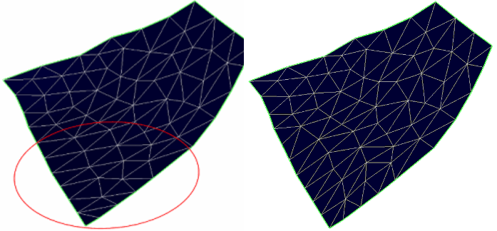
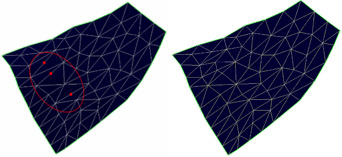
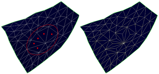
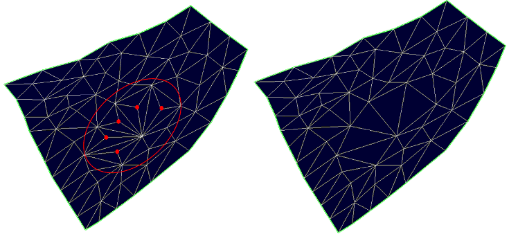
 Move Node Inside Ellipse (Shortcut key: Ctrl+M) Move nodes within an ellipse. The offset of the nodes gradually decreases from the center to the edges of the ellipse. To use the tool:
- Select the tri-mesh and then the Move Node Inside Ellipse tool.
- Click on the node you want to be at the center of the ellipse. This becomes blue and an ellipse is shown around it. All nodes within this ellipse will be moved.
-
Optionally, adjust the size and azimuth of the ellipse by holding down the Ctrl key and dragging one of the axes nodes (black) to adjust size, and hold the Space Bar while dragging one of the axis nodes to adjust azimuth.
The orientation (i.e. dip) of the ellipse cannot be manipulated and is always perpendicular to the normal of the surface at the location of the clicked node. - Hold down the NE, ND or ED keys and drag the node to move it along the North East plane, the North Depth plane or the East Depth plane respectively. You can also move the node along the North, East or Depth axis using the N, E and D keys respectively.
Example: Moving nodes with ellipse. click to enlarge
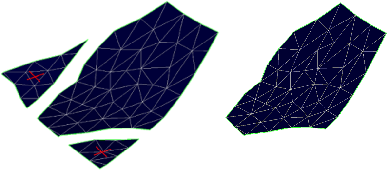
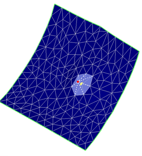
 Move Tri-mesh Patch to Other Tri-mesh (Shortcut key: O) Move a tri-mesh patch to another tri-mesh so that it becomes part of the other tri-mesh. Select the tri-mesh and then the tool. Click on the tri-mesh patch you want to move, and then on the patch you want to move it to. The tri-mesh is integrated with the other tri-mesh.
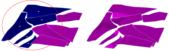
Before and after moving all the blue patches to the purple tri-mesh. click to enlarge
 Move Tri-mesh Patch (Shortcut key: S) Move a tri-mesh patch. Select the tri-mesh and then the tool. Hold down the Ctrl key and drag the patch to move to its new location. Instead of the Ctrl key, hold down the E, D, N key and drag the patch to move it along the East, Depth or North axes respectively.
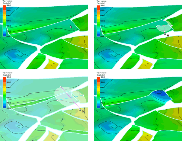
 Extend Tri-mesh (Shortcut key: Ctrl+E) Extend a tri-mesh to another tri-mesh, closing the gap between them and creating a smooth intersection. To use the tool:
- Select the tri-mesh and then the tool. Set the maximum extension if desired.
- Click close to the border of the tri-mesh patch to extend. Blue sticks will show the suggested extension and a line will show the intersection position on the other tri-mesh.
- Optionally, adjust the suggested extension. To do this, click on the blue stick you want to move (the stick becomes red). Click on the other tri-mesh to indicate a new intersection point for the red stick. The stick becomes blue again and moves to the new location. Repeat with other sticks until satisfied with the new intersection.
- Double click on any of the blue sticks to apply the extension.
Max extension Maximum extension distance: The gap will not be closed over those stretches where this value is exceeded (where the gap is wider than the value you enter).
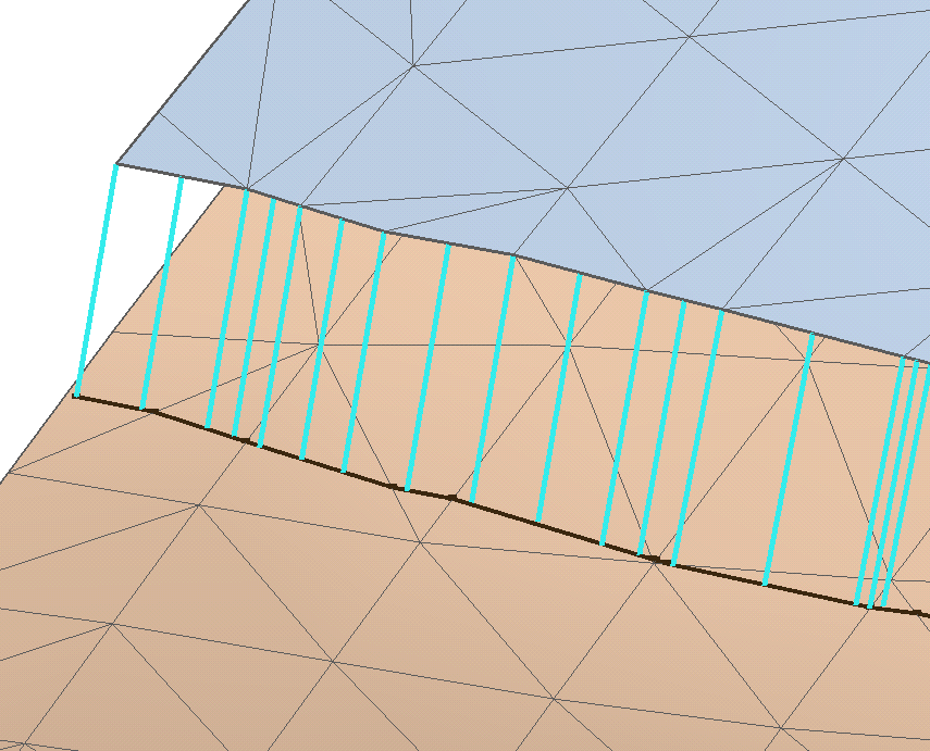
Suggested extension of the blue tri-mesh. click to enlarge
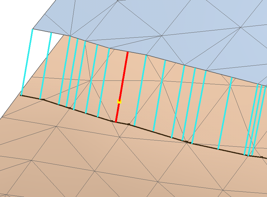
Optionally, you can select a stick to adapt the suggested intersection line. click to enlarge
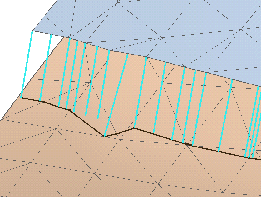
After clicking on the preferred location on the brown tri-mesh, the red stick has moved to the new location (and turned blue again). click to enlarge
After double clicking on any of the blue sticks, the tri-mesh is extended. click to enlarge
 Retract tri-mesh (Shortcut key: Ctrl+R) Clean-up the part of the tri-mesh that sticks (extends) through another tri-mesh. Click close to the border of the tri-mesh patch to retract (yellow sticks indicate the surface that will be retracted). Double click on any of the yellow sticks to apply the retraction.
Max retraction Set a value for the maximum distance allowed for any part of the extension for retraction to be performed. Retraction will occur when, at any point along the extension, the distance between the extension boundary and the intersection is less than this value. If this is the case, the extension will be retracted (entirely, not only the part where the distance is smaller). If this is not the case (when there is no value along the stretch which is smaller than the maximum retraction value), no retraction will occur.